Electronics and Communication Engineering - Networks Analysis and Synthesis
Exercise : Networks Analysis and Synthesis - Section 4
- Networks Analysis and Synthesis - Section 14
- Networks Analysis and Synthesis - Section 27
- Networks Analysis and Synthesis - Section 26
- Networks Analysis and Synthesis - Section 25
- Networks Analysis and Synthesis - Section 24
- Networks Analysis and Synthesis - Section 23
- Networks Analysis and Synthesis - Section 22
- Networks Analysis and Synthesis - Section 21
- Networks Analysis and Synthesis - Section 20
- Networks Analysis and Synthesis - Section 19
- Networks Analysis and Synthesis - Section 18
- Networks Analysis and Synthesis - Section 17
- Networks Analysis and Synthesis - Section 16
- Networks Analysis and Synthesis - Section 15
- Networks Analysis and Synthesis - Section 1
- Networks Analysis and Synthesis - Section 13
- Networks Analysis and Synthesis - Section 12
- Networks Analysis and Synthesis - Section 11
- Networks Analysis and Synthesis - Section 10
- Networks Analysis and Synthesis - Section 9
- Networks Analysis and Synthesis - Section 8
- Networks Analysis and Synthesis - Section 7
- Networks Analysis and Synthesis - Section 6
- Networks Analysis and Synthesis - Section 5
- Networks Analysis and Synthesis - Section 4
- Networks Analysis and Synthesis - Section 3
- Networks Analysis and Synthesis - Section 2
21.
In an R-C circuit, the impedance is 40 Ω at a frequency of 100 Hz. At 200 Hz the impedance should be
Answer: Option
Explanation:
 Since frequency is doubled,
  becomes one-fourth but R2 remains the same.
22.
An RL series circuit has an impedance of 20 Ω when frequency is 25 Hz. At f= 50 Hz, the impedance will be
Answer: Option
Explanation:
Z = R2 + XL2. When frequency is doubled, XL becomes twice but R remains the same.
23.
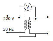
In figure, the voltmeter is ideal. The transformer has two identical windings with perfect coupling. The reading of voltmeter is
Answer: Option
Explanation:
The secondary voltage is equal to primary voltage and the two voltages oppose each other.
24.
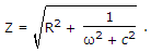
The final value of 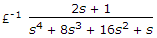 is
is
isAnswer: Option
Explanation:
Use final value theorem.
25.
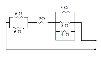
The resistance of the circuit shown is figure is
Answer: Option
Explanation:
The parallel combination of 3, 5 and 4 ohm is short-circuited. Therefore their net resistance is zero.
Quick links
Quantitative Aptitude
Verbal (English)
Reasoning
Programming
Interview
Placement Papers