Electronics and Communication Engineering - Networks Analysis and Synthesis
Exercise : Networks Analysis and Synthesis - Section 2
- Networks Analysis and Synthesis - Section 14
- Networks Analysis and Synthesis - Section 27
- Networks Analysis and Synthesis - Section 26
- Networks Analysis and Synthesis - Section 25
- Networks Analysis and Synthesis - Section 24
- Networks Analysis and Synthesis - Section 23
- Networks Analysis and Synthesis - Section 22
- Networks Analysis and Synthesis - Section 21
- Networks Analysis and Synthesis - Section 20
- Networks Analysis and Synthesis - Section 19
- Networks Analysis and Synthesis - Section 18
- Networks Analysis and Synthesis - Section 17
- Networks Analysis and Synthesis - Section 16
- Networks Analysis and Synthesis - Section 15
- Networks Analysis and Synthesis - Section 1
- Networks Analysis and Synthesis - Section 13
- Networks Analysis and Synthesis - Section 12
- Networks Analysis and Synthesis - Section 11
- Networks Analysis and Synthesis - Section 10
- Networks Analysis and Synthesis - Section 9
- Networks Analysis and Synthesis - Section 8
- Networks Analysis and Synthesis - Section 7
- Networks Analysis and Synthesis - Section 6
- Networks Analysis and Synthesis - Section 5
- Networks Analysis and Synthesis - Section 4
- Networks Analysis and Synthesis - Section 3
- Networks Analysis and Synthesis - Section 2
21.
A two branch tuned circuit has a coil of resistance R and inductance L in one branch and capacitance C in the second branch. If R is increased, the dynamic resistance
Answer: Option
Explanation:
Dynamic resistance = 
22.
A 1 μF capacitor is connected to 12 V battery. The energy stored in the capacitor is
Answer: Option
Explanation:
Energy  x 1 x 10-6 x 144 = 72 x 10-6 J
23.
The poles with greater displacement from the real axis correspond to
Answer: Option
Explanation:
As distance from real axis increases, the frequency of oscillation increases.
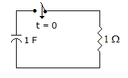
24.
In figure, the capacitor is charged to 1 V. At t = 0 the switch is closed so that i = e-t. When i = 0.37 A, the voltage across capacitor is
Answer: Option
Explanation:
During discharge of capacitor vC = vR = 0.37 x 1 = 0.37 V
25.
In a series RLC circuit p.f is lagging when f < resonance frequency.
Answer: Option
Explanation:
When f < fr, XC > XL and p.f is leading.
Quick links
Quantitative Aptitude
Verbal (English)
Reasoning
Programming
Interview
Placement Papers