Electronics and Communication Engineering - Microwave Communication
Exercise : Microwave Communication - Section 2
26.
For a circular wave guide
Answer: Option
Explanation:
When a circular waveguide is rotated by 90°, the configuration remain the same.
27.
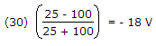
In the given figure the reflected voltage wave after first reflection is
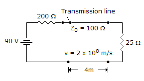
Answer: Option
Explanation:
 .
.
28.
Assertion (A): A half wavelength line can be used as a 1 : 1 transformer.
Reason (R): The input impedance of a half wavelength line is equal to load impedance.
Answer: Option
Explanation:
Since a half wavelength line has an input impedance equal to load impedance, the impedance transformation ratio is 1:1.
29.
The magnitudes of OC and SC input impedances of a transmission line an 100 Ω and 25 Ω. The characteristic impedance is
Answer: Option
Explanation:

30.
A loss less line is terminated in a circular lines are E lines
Answer: Option
Explanation:
 = finite number and VSWR
  = finite number.
Quick links
Quantitative Aptitude
Verbal (English)
Reasoning
Programming
Interview
Placement Papers