Electronics and Communication Engineering - Exam Questions Papers - Discussion
Discussion Forum : Exam Questions Papers - Exam Paper 9 (Q.No. 28)
28.
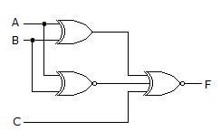
For the output F to be 1 in the logic circuit shown, the input combination should be
Answer: Option
Explanation:
B = A
F = A⊙B⊙C = A⊙A⊙C so,
F = 1 when C = 1.
Discussion:
Be the first person to comment on this question !
Post your comments here:
Quick links
Quantitative Aptitude
Verbal (English)
Reasoning
Programming
Interview
Placement Papers