Electronics and Communication Engineering - Electronic Devices and Circuits
Exercise : Electronic Devices and Circuits - Section 6
- Electronic Devices and Circuits - Section 13
- Electronic Devices and Circuits - Section 24
- Electronic Devices and Circuits - Section 23
- Electronic Devices and Circuits - Section 22
- Electronic Devices and Circuits - Section 21
- Electronic Devices and Circuits - Section 20
- Electronic Devices and Circuits - Section 19
- Electronic Devices and Circuits - Section 18
- Electronic Devices and Circuits - Section 17
- Electronic Devices and Circuits - Section 16
- Electronic Devices and Circuits - Section 15
- Electronic Devices and Circuits - Section 14
- Electronic Devices and Circuits - Section 1
- Electronic Devices and Circuits - Section 12
- Electronic Devices and Circuits - Section 11
- Electronic Devices and Circuits - Section 10
- Electronic Devices and Circuits - Section 9
- Electronic Devices and Circuits - Section 8
- Electronic Devices and Circuits - Section 7
- Electronic Devices and Circuits - Section 6
- Electronic Devices and Circuits - Section 5
- Electronic Devices and Circuits - Section 4
- Electronic Devices and Circuits - Section 3
- Electronic Devices and Circuits - Section 2
41.
Out of 5 M x 8, 1 M x 16, 2 M x 16 and 3M x 8 memories, which memory can store more bits?
Answer: Option
Explanation:
Bits are 40 M, 16 M and 32 M.
42.
A 6 bit ladder A/D converter has input 101001. The output is (assume 0 = 0 V and 1 = 10 V)
Answer: Option
Explanation:
Output =  10 j 6.41 V.
43.
A ripple counter has 4 bits and uses flip flops with propagation delay time of 25 ns. The maximum possible time for change of state will be
Answer: Option
Explanation:
In ripple counter all the delays are added.
44.
A counter has a modulus of 10. The number of flip flops is
Answer: Option
Explanation:
23 = 8 and 24 = 16 Therefore 4 flip-flops are needed. Some states will be skipped to give a modulus of 10.
45.
The counter shown in the given figure is built using 4 -ve edge triggered toggle FFs. The FF can be set asynchronously when R = 0. The combinational logic required to realize a modulo-13 counter is
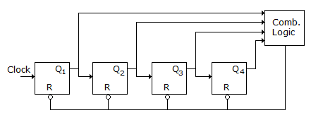
Answer: Option
Explanation:
Counter is modulo-13, it will count up to 15 but due to mod-13, it will be reset at 13, (13)10 = (1101 )2 = Q4 Q3 Q2 Q1.
Quick links
Quantitative Aptitude
Verbal (English)
Reasoning
Programming
Interview
Placement Papers