Electronics and Communication Engineering - Digital Electronics - Discussion
Discussion Forum : Digital Electronics - Section 3 (Q.No. 48)
48.
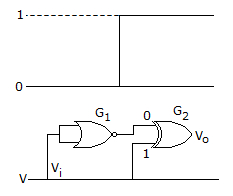
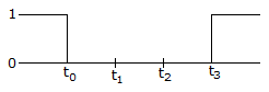
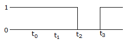
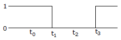
The gates G1 and G2 in the figure have propagation delays of 10 n sec. and 20 n sec. respectively. If the input Vi makes an output change from logic 0 to 1 at time t = t0 then the output wavefrom V0 is
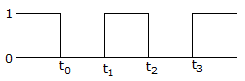
Answer: Option
Explanation:
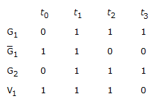
Truth table are as follows.
Discussion:
4 comments Page 1 of 1.
Jackie Chan said:
1 month ago
@All.
I think the question is wrong, as the circuit is designed so that the output is always 1.
It can not be switched from 0 to 1 and 1 to 0, as it only gives an output of 1 when the inputs are different, like 0, 1 or 1, 0.
In this case, the inputs to the second gate will always be different because both are the same input, with one being the complement of the other.
I think the question is wrong, as the circuit is designed so that the output is always 1.
It can not be switched from 0 to 1 and 1 to 0, as it only gives an output of 1 when the inputs are different, like 0, 1 or 1, 0.
In this case, the inputs to the second gate will always be different because both are the same input, with one being the complement of the other.
Kalitakaushik5@gmail.com said:
1 decade ago
I didn't understand this V1 1110 then answer should be B.
Mohit said:
10 years ago
Yes, the answer should be B.
Pavan said:
9 years ago
Yes, the answer is B.
Post your comments here:
Quick links
Quantitative Aptitude
Verbal (English)
Reasoning
Programming
Interview
Placement Papers