Electronics and Communication Engineering - Digital Electronics - Discussion
Discussion Forum : Digital Electronics - Section 1 (Q.No. 13)
13.
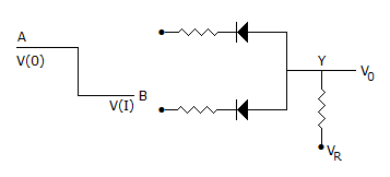
The circuit in the given figure is
Answer: Option
Explanation:
Since V(I) is lower state than V(0) it is a negative logic circuit. Since diodes are in reversed parallel, it is an AND gate.
Note: In Boolean algebra it is recognized that a positive logic OR is a negative logic AND. Similarly a positive logic AND is a negative logic OR.
Discussion:
29 comments Page 2 of 3.
Gaurav pandey said:
10 years ago
Negative logic AND gate is the right answer.
Pranab said:
9 years ago
It is -ve logic OR gate and it is also +ve logic AND gate.
Mohd Salim said:
9 years ago
It should be a Negative logic AND gate.
Chand said:
9 years ago
Positive logic AND, Negative logic OR both.
Sai said:
9 years ago
How we find AND OR using diodes?
Lavanya said:
9 years ago
Which is the correct answer and how? Please explain it clearly.
Tamil said:
9 years ago
@Lavanya.
The pulse is low to high so this is negative and the diodes are reversed. So this is negative logic AND gate. Suppose the diodes are forward this logic is negative logic OR gate.
The pulse is low to high so this is negative and the diodes are reversed. So this is negative logic AND gate. Suppose the diodes are forward this logic is negative logic OR gate.
Arnab said:
9 years ago
It is only positive logic AND gate.
Ayush Kumar said:
9 years ago
Why are you confused friends?
The right answer is negative logic AND gate because diode is reversed.
The right answer is negative logic AND gate because diode is reversed.
Nabanita said:
9 years ago
It is neg logic or gate as the diode is reverse biased it follows the following table:
0 0 = 0 (as the current flows to both of the diode the v0 output is zero)
0 1 = 0
1 0 = 0
1 1 = 1
it is pos logic and gate.
so it is neg logic or.
0 0 = 0 (as the current flows to both of the diode the v0 output is zero)
0 1 = 0
1 0 = 0
1 1 = 1
it is pos logic and gate.
so it is neg logic or.
Post your comments here:
Quick links
Quantitative Aptitude
Verbal (English)
Reasoning
Programming
Interview
Placement Papers