Electronics and Communication Engineering - Analog Electronics
Exercise : Analog Electronics - Section 7
- Analog Electronics - Section 11
- Analog Electronics - Section 21
- Analog Electronics - Section 20
- Analog Electronics - Section 19
- Analog Electronics - Section 18
- Analog Electronics - Section 17
- Analog Electronics - Section 16
- Analog Electronics - Section 15
- Analog Electronics - Section 14
- Analog Electronics - Section 13
- Analog Electronics - Section 12
- Analog Electronics - Section 1
- Analog Electronics - Section 10
- Analog Electronics - Section 9
- Analog Electronics - Section 8
- Analog Electronics - Section 7
- Analog Electronics - Section 6
- Analog Electronics - Section 5
- Analog Electronics - Section 4
- Analog Electronics - Section 3
- Analog Electronics - Section 2
36.
The h parameter equivalent circuit of BJT has one voltage source and one current source.
37.
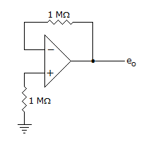
The voltage eo indicated in the figure has been measured by an ideal voltmeter. Which of the following can be calculated?
38.
In an RC-coupled amplifier for improving the low frequency response
39.
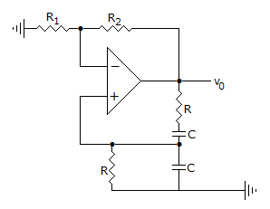
The circuit of figure is
40.
The minimum gate source voltage that creates the n-type inversion layer is called
Quick links
Quantitative Aptitude
Verbal (English)
Reasoning
Programming
Interview
Placement Papers