Electronics and Communication Engineering - Analog Electronics
Exercise : Analog Electronics - Section 5
- Analog Electronics - Section 11
- Analog Electronics - Section 21
- Analog Electronics - Section 20
- Analog Electronics - Section 19
- Analog Electronics - Section 18
- Analog Electronics - Section 17
- Analog Electronics - Section 16
- Analog Electronics - Section 15
- Analog Electronics - Section 14
- Analog Electronics - Section 13
- Analog Electronics - Section 12
- Analog Electronics - Section 1
- Analog Electronics - Section 10
- Analog Electronics - Section 9
- Analog Electronics - Section 8
- Analog Electronics - Section 7
- Analog Electronics - Section 6
- Analog Electronics - Section 5
- Analog Electronics - Section 4
- Analog Electronics - Section 3
- Analog Electronics - Section 2
6.
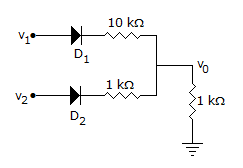
In the circuit of figure both diodes are ideal. If v1 = 10 V and v2 = 10 V which diode will conduct?
Answer: Option
Explanation:
Both D1 and D2 are forward biased.
7.
The output impedance of an ideal op-amp is
Answer: Option
Explanation:
An ideal op-amp has zero output impedance and can deliver any amount of load current without any voltage drop.
8.
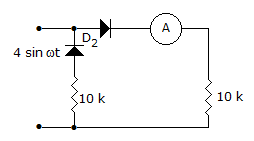
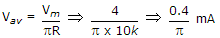
In the circuit of the given figure, assume that the diodes are ideal and the meter is an average indicating ammeter, the ammeter will read
0.42 A
0.4 A

0.4/p mA
Answer: Option
Explanation:
Ammeter will real during +ve half cycle only and
 .
.
9.
A virtual ground is a ground for
Answer: Option
Explanation:
No current can flow through virtual ground. However voltage is zero.
10.
As compared to a full wave diode rectifier circuit using centre tapped transformer, the bridge diode rectifier circuit has the main advantage of
Answer: Option
Explanation:
For bridge rectifier, peak inverse voltage is equal to peak value of ac voltage while for the circuit using centre tapped transformer peak inverse voltage is 2 Em.
Quick links
Quantitative Aptitude
Verbal (English)
Reasoning
Programming
Interview
Placement Papers