Electronics and Communication Engineering - Analog Electronics
Exercise : Analog Electronics - Section 1
- Analog Electronics - Section 11
- Analog Electronics - Section 21
- Analog Electronics - Section 20
- Analog Electronics - Section 19
- Analog Electronics - Section 18
- Analog Electronics - Section 17
- Analog Electronics - Section 16
- Analog Electronics - Section 15
- Analog Electronics - Section 14
- Analog Electronics - Section 13
- Analog Electronics - Section 12
- Analog Electronics - Section 1
- Analog Electronics - Section 10
- Analog Electronics - Section 9
- Analog Electronics - Section 8
- Analog Electronics - Section 7
- Analog Electronics - Section 6
- Analog Electronics - Section 5
- Analog Electronics - Section 4
- Analog Electronics - Section 3
- Analog Electronics - Section 2
16.
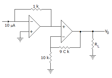
The output V0 in figure is
Answer: Option
Explanation:
Input to non-inverting op-amp is -10 x 10-6 x 103 = -10 mV.
Therefore output = 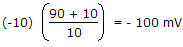 = -100 mV.
17.
In a CE amplifier the input impedance is equal to the ratio of
Answer: Option
Explanation:
Input is applied to base with emitter grounded. The input impedance is the ratio of ac base voltage to ac base current.
18.
For a system to work, as oscillator the total phase shift of the loop gain must be equal to
Answer: Option
Explanation:
Gain of system with + ve feedback = 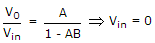 for oscillation
but V0 ≠ 0
so, that 1 - AB = 0  AB = 1 ∠0° or 360°.
19.
An amplifier has a large ac input signal. The clipping occurs on both the peaks. The output voltage will be nearly a
Answer: Option
Explanation:
When a sinusoidal voltage is clipped on both sides it resembles a square wave.
20.
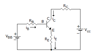
The transistor of following figure in Si diode with a base current of 40 μA and ICBO = 0, if VBB = 6V, RE = 2 kΩ and β = 90, IBQ = 20 μA then RB =
Answer: Option
Explanation:
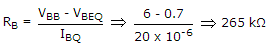 .
.
Quick links
Quantitative Aptitude
Verbal (English)
Reasoning
Programming
Interview
Placement Papers