Digital Electronics - MSI Logic Circuits - Discussion
Discussion Forum : MSI Logic Circuits - General Questions (Q.No. 3)
3.
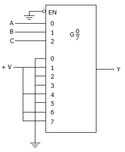
Refer to the figure given below. The logic function generator being implemented with the multiplexer in this circuit produces a constant LOW on the output. The ABC inputs are checked and appear to be pulsing; also, the 0–7 and EN inputs are checked with the scope and all appear to be at 0 V. A check with the DMM confirms that power is on. What is the problem, and what should be done to correct it?
Discussion:
2 comments Page 1 of 1.
Anbu said:
1 decade ago
Enable Pin is grounded. It need to be Vcc.
Mounika said:
6 years ago
Could you explain the answer, please?
Post your comments here:
Quick links
Quantitative Aptitude
Verbal (English)
Reasoning
Programming
Interview
Placement Papers