Digital Electronics - Memory and Storage - Discussion
Discussion Forum : Memory and Storage - General Questions (Q.No. 3)
3.
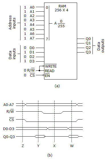
Refer to the given figures (a) and (b). A logic analyzer is used to check the circuit in figure (a) and displays the waveforms shown in figure (b). The actual analyzer display shows all four data outputs, Q0-Q3. The analyzer's cursor is placed at position X and all four of the data output lines show a LOW level output. What is wrong, if anything, with the circuit?
Nothing is wrong, according to the display. The outputs are in the open state and should show zero output voltage.
The circuit is in the READ mode and the outputs, Q0-Q3, should reflect the contents of the memory at that address. The chip is defective; replace the chip.
The circuit is in the  mode and should be writing the contents of the selected address to Q0–Q3.
mode and should be writing the contents of the selected address to Q0–Q3.The Q0–Q3 lines can be either LOW or HIGH, since the chip is in the tristate mode in which case their level is unpredictable.
Discussion:
Be the first person to comment on this question !
Post your comments here:
Quick links
Quantitative Aptitude
Verbal (English)
Reasoning
Programming
Interview
Placement Papers