Digital Electronics - Counters - Discussion
Discussion Forum : Counters - General Questions (Q.No. 30)
30.
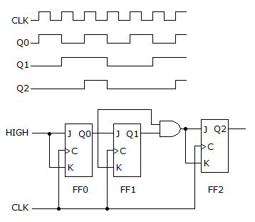
A four-channel scope is used to check the counter in the figure given below. Are the displayed waveforms correct?
Discussion:
6 comments Page 1 of 1.
Raghavendra S said:
1 decade ago
case(1):
q2 will go high at falling edges of qo & q1.
Assume clock skew=0 for simplicity of analysis & take "clock to data delay" under consideration.so we have to consider inputs to "2 right side ff's" will be previous value.
case(2):
if "clock to data delay" is considered to be 0,then q1 & q2 both wave forms are wrong here.
Please correct if anybody found I am wrong.
Jeeva said:
10 years ago
Input of the JK f/f is high. So, the output is in toggle state. Check the waveform based on the toggle concept.
Sandeep said:
1 decade ago
Q2 should only change at rising/falling edge of its flip flop's input. Please correct me if I am wrong.
Akshay said:
1 decade ago
I think the only error is in Q2, at the end when it transits despite Q1 being 0.
Supriya V G said:
4 years ago
What is the K input of FF1? Please tell me.
Anirban said:
1 decade ago
This simply follows an up counter.
Post your comments here:
Quick links
Quantitative Aptitude
Verbal (English)
Reasoning
Programming
Interview
Placement Papers