Digital Electronics - Counters - Discussion
Discussion Forum : Counters - General Questions (Q.No. 17)
17.
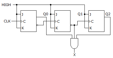
What decimal value is required to produce an output at "X" ?
Discussion:
13 comments Page 1 of 2.
Ram said:
2 years ago
No of flip flops are 3 because flip flop is a one-bit storage element. So, the answer is 5 (101).
Vijaya said:
8 years ago
Thank you @Madhuri.
(1)
Sahaja said:
8 years ago
Leave everything and just check the and gate. It has 3 inputs in the circuit right!
The output of and the gate will be true only if all of its inputs are 1.
Then, check all the 3 inputs to where those were connected.
1st input ----to positive output Q0.
2nd input-----to negative output Q1.
3rd input-------to positive output Q2.
We are taking 2nd input from the bubble i.e., negative that means the original output Q2 shoud be 0 to give 1 after complementing.
This gives the answer 1015, 5.
The output of and the gate will be true only if all of its inputs are 1.
Then, check all the 3 inputs to where those were connected.
1st input ----to positive output Q0.
2nd input-----to negative output Q1.
3rd input-------to positive output Q2.
We are taking 2nd input from the bubble i.e., negative that means the original output Q2 shoud be 0 to give 1 after complementing.
This gives the answer 101
HARINI said:
9 years ago
The given ckt is 3-bit ripple counter.
This counter o/p takes from Q0, Q1 & Q2.
it counts from 000 to 111 all these 3 o/p Q0, Q1^ & Q2 are giving to AND gate it produces X o/p.
For AND gate if all input is high '1' then o/p is high Otherwise low '0';
For o/p X '1' means(here x is AND o/p).
for this ckt
Q0 Q1^ Q2
1 0 1
only at this state all i/p of AND connected to ligic1.
so X is high only at this state.
its decimal value is 5.
Answer is 5.
All i/p must be '1'.
Madhuri said:
1 decade ago
JK flip-flop operation.
Here, notice that both the inputs i.e., J and K are tied together and given. Therefore the only possible input conditions for JK flipflop are (j=0& k=0) or (j =1 and k=1).
Now we are in J=1, K=1 condition, which means the present output Q should be the toggled version of previous state output.
The previous state output will obviously be for j= 0 and k=0 input condition. The output, in this case, will be 0 only (retains the previous state for j=0 and k=0 condition) - check truth table for jk flip flop.
This is how the first flip flop's output becomes 1 (toggle of previous state output5, 0).
Now consider second flip-flop, the same condition repeats but the output is taken from Qbar pin of the flipflop. Therefore second flipflop's output is 0.
The third one follows similar explanation as given for first flip-flop. Output turns out to be 1 again.
Here, notice that both the inputs i.e., J and K are tied together and given. Therefore the only possible input conditions for JK flipflop are (j=0& k=0) or (j =1 and k=1).
Now we are in J=1, K=1 condition, which means the present output Q should be the toggled version of previous state output.
The previous state output will obviously be for j= 0 and k=0 input condition. The output, in this case, will be 0 only (retains the previous state for j=0 and k=0 condition) - check truth table for jk flip flop.
This is how the first flip flop's output becomes 1 (toggle of previous state output
Now consider second flip-flop, the same condition repeats but the output is taken from Qbar pin of the flipflop. Therefore second flipflop's output is 0.
The third one follows similar explanation as given for first flip-flop. Output turns out to be 1 again.
(1)
Nitin said:
1 decade ago
Please explain anyone?
Vinay said:
1 decade ago
I want to get a right answer please explain anyone.
Kavi said:
1 decade ago
I couldn't understand can anyone explain clearly?
Siva chithra said:
1 decade ago
Please give me the correct explanation sir.
Satyendra singh said:
1 decade ago
For AND gate if all input is high '1' then o/p is high.
Otherwise low '0';
For o/p '1' means(here x o/p).
All i/p must be '1';
Also in this ckt mention that.
Here,
For Q0 = 1.
Q1 = 0(bcg ~Q=1).
Q2 = 1 then.
o/p is 'high' or 'X'.
Otherwise low '0';
For o/p '1' means(here x o/p).
All i/p must be '1';
Also in this ckt mention that.
Here,
For Q0 = 1.
Q1 = 0(bcg ~Q=1).
Q2 = 1 then.
o/p is 'high' or 'X'.
Post your comments here:
Quick links
Quantitative Aptitude
Verbal (English)
Reasoning
Programming
Interview
Placement Papers