Mechanical Engineering - Theory of machines - Discussion
Discussion Forum : Theory of machines - Section 4 (Q.No. 44)
44.
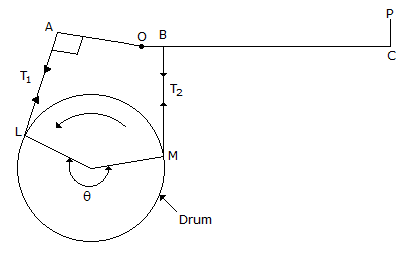
For the brake to be self locking, the force P at C shown in the below figure, should
Discussion:
6 comments Page 1 of 1.
Vijay hcet said:
10 years ago
Answer should be option C.
Pintu said:
10 years ago
T1 is tight side and T2 is slack side and the drum rotates anticlockwise, so P is act in a downward direction.
Ashu said:
8 years ago
No, the Answer is c.
Sdg said:
8 years ago
The Correct answer is C.
Nailesh said:
7 years ago
The correct answer is C. .
Ganeshr said:
5 years ago
Rn x X = PL + μaRn.
Rn = Normal reaction, P = Applied force, L = lever length.
X = Distance of block from the hinge, μ= coefficient of friction, a = distance of drum from the hinge.
In the above equation when frictional force adds to the braking torque. In other words, the frictional torque and braking torque are in the same direction its a self-locking brake.
In the above equation when X < μa, P becomes negative
Hence, P is not required for braking and the brake gets applied on its own. It is called a self-energizing brake.
So, the Correct answer is C.
Post your comments here:
Quick links
Quantitative Aptitude
Verbal (English)
Reasoning
Programming
Interview
Placement Papers