Circuit Simulator - RLC Circuit
Why should I learn to use the circuit simulator to design RLC Circuit circuits?
Learn how to use circuit simulator software to design your own RLC Circuit circuits.
Where can I get a RLC Circuit circuit diagram with an explanation?
IndiaBIX provides numerous RLC Circuit circuit diagrams with detailed explanations and working principles.
How do I design a RLC Circuit circuit with this circuit simulator?
You can easily design RLC Circuit circuit diagrams by practising with the given circuit simulator. With this online circuit simulator, you can design and simulate your own electronic circuits.
RLC Circuit
Circuit Description:
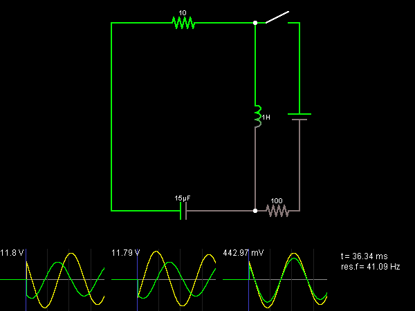
This is an RLC circuit, which is an oscillating circuit consisting of a resistor, capacitor, and inductor connected in series. The capacitor is charged initially; the voltage of this charged capacitor causes a current to flow in the inductor to discharge the capacitor. Once the capacitor is discharged, the inductor resists any change in the current flow, causing the capacitor to be charged again with the opposite polarity. The voltage in the capacitor eventually causes the current flow to stop and then flow in the opposite direction. The result is an oscillation, or resonance.
The voltages and currents in the inductor, capacitor, and resistor are shown in the scopes below the circuit (voltage is shown in green, current in yellow). The resonance frequency depends on the capacitance and inductance in the circuit and is shown in the lower-right corner (as res.f).
After a while, the oscillation will die down, because of the resistor. Close the switch momentarily to get it going again.
Discussion:
3 comments Page 1 of 1.
Manank Bhavsar said:
9 years ago
In which software the above simulation had done?
(5)
Priyanka said:
1 decade ago
Will you explain me why only capacitor gets charged first in this circuit. Do inductor may also get charged first. As both are connected to positive terminal of supply.
(1)
Gaurav said:
1 decade ago
Good site for learners.
(6)
Post your comments here:
Quick links
Quantitative Aptitude
Verbal (English)
Reasoning
Programming
Interview
Placement Papers