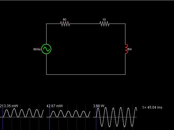
Circuit Simulator - Power Factor
Power Factor

Circuit Description:
This circuit shows an inductor being driven by an AC voltage. The colors indicate power consumption; red means that a component is consuming power, and green means that the component is contributing power. The left side of the circuit represents the power company's side, and the right side represents a factory (with a large induction motor).
The highly inductive load is causing the power company to work a lot harder than normal for a given amount of power delivered. The graph on the left indicates the power lost in the power company's equipment (the resistor at top left). The graph in the middle is the power delivered to the factory. The graph on the right is the power delivered to the inductor (and then returned, causing the time average of power delivered to be zero).
Even though a peak power of 40 mW is being delivered to the factory, 200 mW is being dissipated in the power company's wires. This can happen whenever power factor is less than 1, and power companies usually charge extra when this happens.
Discussion:
4 comments Page 1 of 1.
S.PONNAYIRA SUNDARA VEL said:
1 decade ago
From the energy meter measure the real power (P) & P.F.
(P.F = value = 0.00 to 1).
Then calculate the S (Apparent Power) = P/P.F.
Then Calculate the Q (Reactive Power) = SQR RooT of (SQR of S - SQR of P) = Answer in VAr = WCV2,
Where.
W = Omega = 2*Pi*f.
pi = 3.14.
f = 50 Hz.
V2 = SQR of V = V*V.
C = Capacitance.
Then Find Capacitance Value to Improve the power Factor.
(5)
Tushar kafare said:
2 decades ago
When power factor is at maximum value?
(2)
Manish said:
1 decade ago
When angle between Voltage and the Current is zero. At that time the power factor is unity.
Thanks.
Thanks.
(2)
R.NATHIYA said:
1 decade ago
How to calculate power factor of a load (during power consumption)? Is there any circuit for that?
(2)
Post your comments here:
Quick links
Quantitative Aptitude
Verbal (English)
Reasoning
Programming
Interview
Placement Papers