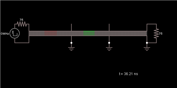
Circuit Simulator - Mismatched transmission lines (Pulse)
Why should I learn to use the circuit simulator to design Mismatched transmission lines (Pulse) circuits?
Learn how to use circuit simulator software to design your own Mismatched transmission lines (Pulse) circuits.
Where can I get a Mismatched transmission lines (Pulse) circuit diagram with an explanation?
IndiaBIX provides numerous Mismatched transmission lines (Pulse) circuit diagrams with detailed explanations and working principles.
How do I design a Mismatched transmission lines (Pulse) circuit with this circuit simulator?
You can easily design Mismatched transmission lines (Pulse) circuit diagrams by practising with the given circuit simulator. With this online circuit simulator, you can design and simulate your own electronic circuits.
Mismatched transmission lines (Pulse)

Circuit Description:
This is a simple circuit showing three mismatched transmission lines. The two lines on the end are 75 ohms, and the middle line is 500 ohms. Waves traveling down the line are reflected at transmission line boundaries.
Discussion:
1 comments Page 1 of 1.
Engr. Hassan said:
1 decade ago
Can some one help me explain in details mismatched in transmission line.
The courses, loses, solution and problem solving. With reference please.
Thanks.
The courses, loses, solution and problem solving. With reference please.
Thanks.
(3)
Post your comments here:
Quick links
Quantitative Aptitude
Verbal (English)
Reasoning
Programming
Interview
Placement Papers