Circuit Simulator - Current Mirror (with transistors)
Why should I learn to use the circuit simulator to design Current Mirror (with transistors) circuits?
Learn how to use circuit simulator software to design your own Current Mirror (with transistors) circuits.
Where can I get a Current Mirror (with transistors) circuit diagram with an explanation?
IndiaBIX provides numerous Current Mirror (with transistors) circuit diagrams with detailed explanations and working principles.
How do I design a Current Mirror (with transistors) circuit with this circuit simulator?
You can easily design Current Mirror (with transistors) circuit diagrams by practising with the given circuit simulator. With this online circuit simulator, you can design and simulate your own electronic circuits.
Current Mirror (with transistors)
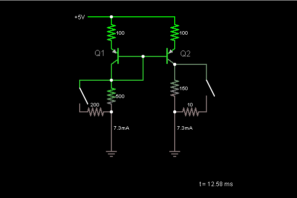
Circuit Description:
This is a current mirror, a device that uses the current in one half of the circuit to control the current flow in the other half. The current is the same in both halves. The switch on the left changes the current flow in the left half, which is mirrored in the right half. The switch on the right causes the resistor to be bypassed, but the current mirror ensures that the flow of current does not change.
Q1's emitter-base junction acts like a diode. The current through it is set by the resistor network below it. Wiring the base to the collector ensures that the base current can flow, so the transistor can stay in the active mode. Since Q1's base is wired to Q2's, they are at the same voltage, so Q2's emitter-base junction must have the same amount of current flowing through it. (It acts like a diode, so the current is determined by the voltage across it.)
Both halves of the circuit have nearly the same current flowing through them. The only difference is that the base currents from Q1 and Q2 flow through the left half, and not the right half. We use high-beta transistors in this circuit to make these base currents as small as possible.
Discussion:
Be the first person to comment on this question !
Post your comments here:
Quick links
Quantitative Aptitude
Verbal (English)
Reasoning
Programming
Interview
Placement Papers