Circuit Simulator - 555 Schmitt Trigger (inverting)
Why should I learn to use the circuit simulator to design 555 Schmitt Trigger (inverting) circuits?
Learn how to use circuit simulator software to design your own 555 Schmitt Trigger (inverting) circuits.
Where can I get a 555 Schmitt Trigger (inverting) circuit diagram with an explanation?
IndiaBIX provides numerous 555 Schmitt Trigger (inverting) circuit diagrams with detailed explanations and working principles.
How do I design a 555 Schmitt Trigger (inverting) circuit with this circuit simulator?
You can easily design 555 Schmitt Trigger (inverting) circuit diagrams by practising with the given circuit simulator. With this online circuit simulator, you can design and simulate your own electronic circuits.
555 Schmitt Trigger (inverting)
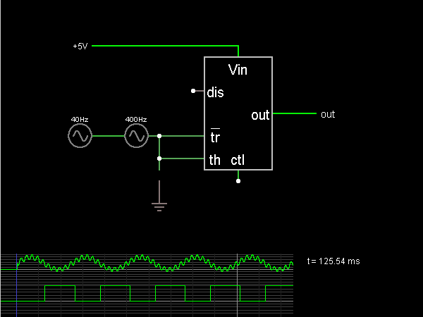
Circuit Description:
This circuit is a Schmitt Trigger, a type of comparator, built using a 555 timer chip for some reason. It measures the input to see if it is above or below a certain threshold. The threshold varies to make it less likely that the output will switch rapidly back and forth due to a noisy input near the threshold.
This circuit uses the fact that a 555 output goes high when the trigger input goes below 1/3 Vin, and the output goes low when the threshold input goes above 2/3 Vin.
This circuit uses the fact that a 555 output goes high when the trigger input goes below 1/3 Vin, and the output goes low when the threshold input goes above 2/3 Vin.
Discussion:
Be the first person to comment on this question !
Post your comments here:
Quick links
Quantitative Aptitude
Verbal (English)
Reasoning
Programming
Interview
Placement Papers