Electronics and Communication Engineering - Networks Analysis and Synthesis - Discussion
Discussion Forum : Networks Analysis and Synthesis - Section 9 (Q.No. 22)
22.
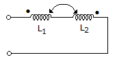
The equivalent inductance measured between the terminals 1 and 2 for the circuit shown in the figure is
Answer: Option
Explanation:
L = L1 + L2 - 2M because currents are opposing.
Discussion:
Be the first person to comment on this question !
Post your comments here:
Quick links
Quantitative Aptitude
Verbal (English)
Reasoning
Programming
Interview
Placement Papers