Electronics and Communication Engineering - Networks Analysis and Synthesis - Discussion
Discussion Forum : Networks Analysis and Synthesis - Section 27 (Q.No. 9)
9.
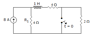
In figure, the switch has been in closed position for a long time. At t = 0, the switch is opened. At t = 0+, the current R1 is
Discussion:
3 comments Page 1 of 1.
Soundarya said:
9 years ago
But in question, they didn't mention the steady state value how you're assuming the steady state condition? Please give some more explanation.
Dhanush said:
9 years ago
t = 0- Circuit is at steady state inductor behaves as a short circuit, I(0+) = I(0-).
Dhoni said:
7 years ago
And should be 8 Ampere.
Post your comments here:
Quick links
Quantitative Aptitude
Verbal (English)
Reasoning
Programming
Interview
Placement Papers