Electronics and Communication Engineering - Networks Analysis and Synthesis - Discussion
Discussion Forum : Networks Analysis and Synthesis - Section 2 (Q.No. 29)
29.
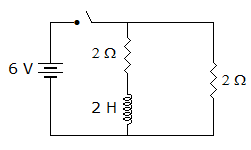
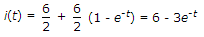
The circuit in figure is switched on at t = 0. At any time t, i(t) =
Answer: Option
Explanation:
Discussion:
3 comments Page 1 of 1.
Gaurav pandey said:
9 years ago
C will be the right answer.
ElectronVolt said:
9 years ago
B is the right answer. At infinite time the inductor will behave like a short circuit so in that case the equivalent circuit resistance = two 2 ohms in parallel which is equal to 1. So current would be 6 amps in steady state.
Anitha said:
5 years ago
@Gaurav Pandey.
Please give an explanation for option C.
Please give an explanation for option C.
Post your comments here:
Quick links
Quantitative Aptitude
Verbal (English)
Reasoning
Programming
Interview
Placement Papers