Electronics and Communication Engineering - Microwave Communication
Assertion (A): A coaxial line is a non-radiating line.
Reason (R): In a coaxial line the electric and magnetic fields are confined to the region between the concentric conductors.
Since the fields are confined, there is no radiation.
It uses a single cavity resonator for generating microwave oscillations.
Its parts are electron gun, resonator, repeller and output coupling.
It operates on the principle of positive feed back.
The repeller electrode is at negative potential and sends the partially bunched electron beam back to resonator cavity.
This positive feedback supports oscillations. Its feature are:
1. Frequency range - 2 to 100 GHz
2. Power output - 10 MW to about 2 W
3. Efficiency - 10 - 20 %
Its applications include radar receivers, local oscillator in microwave devices, oscillator for microwave measurements in laboratories etc.
 and is independent of line length.
Since all ports matched, input SWR = 1. No power is reflected and Pin = P4 = 1 W.
This power splits between ports 1 and 2. Therefore P1 = P2 = 0.5 Ω, P3 = 0.
Hz = 0
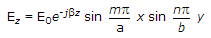
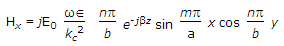
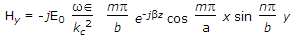
Ex = ± ZTM Hy
Ey = ± ZTM Hx
where E0 is the amplitude of the wave.
The expressions for β, λc, fc, λg, a are the same as for TE waves.
For TM wave the lowest cut off frequency in rectangular wave guide is for TM11 mode.
If  , the cutoff frequency for TM11 mode is about 12% more than that for TE20 mode.