Electronics and Communication Engineering - Exam Questions Papers - Discussion
Discussion Forum : Exam Questions Papers - Exam Paper 5 (Q.No. 10)
10.
An electrical system and its signal-flow graph representation are shown in figure (a) and (b) respectively
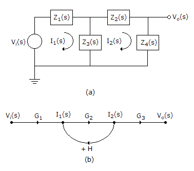
The values of G2 and H, respectively are
The values of G2 and H, respectively are
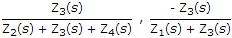
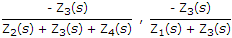
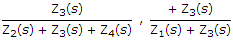
Answer: Option
Explanation:
Vi(s) = Z1I1 + Z3(I1 - I2) ...(i)
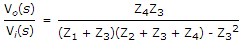
V0(s) = Z4I2
I2(Z3 + Z2 + Z4) = Z3I1 ...(ii)
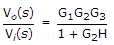
From signal flow graph
I2 = I1G2 ⇒ 
Hence, 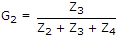
 ...(iii)
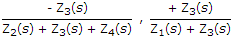
 From SFG ...(iv)
From (ii), (iii), (iv) we get H.
Discussion:
Be the first person to comment on this question !
Post your comments here:
Quick links
Quantitative Aptitude
Verbal (English)
Reasoning
Programming
Interview
Placement Papers