Electronics and Communication Engineering - Exam Questions Papers - Discussion
Discussion Forum : Exam Questions Papers - Exam Paper 10 (Q.No. 3)
3.
The circuit shown in the figure has 4 boxes each described by inputs P, Q, R and outputs Y, Z with
Y = P ⊕ Q ⊕ R, Z = RQ + P R + Q P
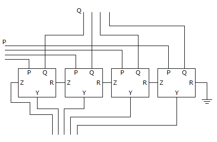
The circuit is a
Y = P ⊕ Q ⊕ R, Z = RQ + P R + Q P
The circuit is a
Answer: Option
Explanation:
Let P = 1101 Q = 1101
Yn = Pn ⊕ Qn ⊕ Rn
Z = Rn Qn + Pn Rn + Qn Pn
Constructing truth table
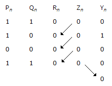
So that, Rn + 1 = Zn 1 ≥ n ≥ 3
Z4 = R5(MSB)
Hence, output is 00010 which show that it is a 4 bit subtractor giving P - Q.
Discussion:
Be the first person to comment on this question !
Post your comments here:
Quick links
Quantitative Aptitude
Verbal (English)
Reasoning
Programming
Interview
Placement Papers