Electronics and Communication Engineering - Electronic Devices and Circuits
Exercise : Electronic Devices and Circuits - Section 7
- Electronic Devices and Circuits - Section 13
- Electronic Devices and Circuits - Section 24
- Electronic Devices and Circuits - Section 23
- Electronic Devices and Circuits - Section 22
- Electronic Devices and Circuits - Section 21
- Electronic Devices and Circuits - Section 20
- Electronic Devices and Circuits - Section 19
- Electronic Devices and Circuits - Section 18
- Electronic Devices and Circuits - Section 17
- Electronic Devices and Circuits - Section 16
- Electronic Devices and Circuits - Section 15
- Electronic Devices and Circuits - Section 14
- Electronic Devices and Circuits - Section 1
- Electronic Devices and Circuits - Section 12
- Electronic Devices and Circuits - Section 11
- Electronic Devices and Circuits - Section 10
- Electronic Devices and Circuits - Section 9
- Electronic Devices and Circuits - Section 8
- Electronic Devices and Circuits - Section 7
- Electronic Devices and Circuits - Section 6
- Electronic Devices and Circuits - Section 5
- Electronic Devices and Circuits - Section 4
- Electronic Devices and Circuits - Section 3
- Electronic Devices and Circuits - Section 2
6.
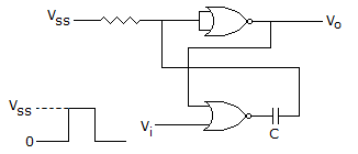
The circuit in the figure is has two CMOS-NOR gates. This circuit functions as a
Answer: Option
Explanation:
It is simple monostable multivibrator.
7.
A 6 bit DAC uses binary weighted resistors. If MSB resistor is 20 k ohm, the value of LSB resistor is
Answer: Option
Explanation:
Resistances are R, 2R, 4R, 8R, 16R and 32R.
LSB resistance = 32R = 32 x 20 = 640 K ohm.
8.
A 6 bit dual slope A/D converter uses a reference of -6v and a 1 MHz clock. It uses a fixed count of 40 (101000). Then, what will be input, if the output register shows 100111 at the end of conversion.
Answer: Option
Explanation:
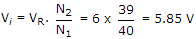
I/P voltage and reference voltage arc of opposite polarity.
9.
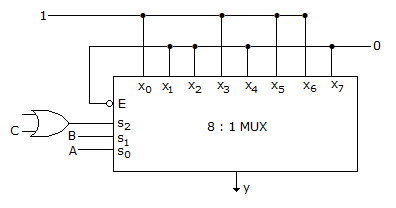
In the TTL circuit in the figure, S2 to S0 are select lines and X7 to X0 are input lines. S0 and X0 are LSBs. The output Y is
Answer: Option
Explanation:
The MUX is made up of TTL circuit. For TTL circuit open terminal is taken high, since S2 select line is connected to OR gate whose one terminal connected to C and the other is open (high) so OR gate output is S2 = 1 + C = 1.
S2 = 1 S1(B) S0(A)  Y
1       0     0     0
1       0     1     1
1       1     0     1
1       1     1     0
Y = S0⊕S1 => A⊕B.
10.
The number of accumulators in 6800 are
Quick links
Quantitative Aptitude
Verbal (English)
Reasoning
Programming
Interview
Placement Papers