Electronics and Communication Engineering - Digital Electronics - Discussion
Discussion Forum : Digital Electronics - Section 7 (Q.No. 9)
9.
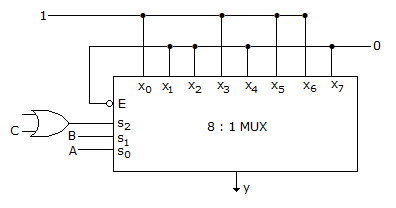
In the TTL circuit in the figure, S2 to S0 are select lines and X7 to X0 are input lines. S0 and X0 are LSBs. The output Y is
Answer: Option
Explanation:
The MUX is made up of TTL circuit. For TTL circuit open terminal is taken high, since S2 select line is connected to OR gate whose one terminal connected to C and the other is open (high) so OR gate output is S2 = 1 + C = 1.
S2 = 1 S1(B) S0(A)  Y
1       0     0     0
1       0     1     1
1       1     0     1
1       1     1     0
Y = S0⊕S1 => A⊕B.
Discussion:
3 comments Page 1 of 1.
Saif said:
3 years ago
Can anyone provide me a clear explanation?
(1)
Shalabh said:
3 years ago
@All.
Since S2 is always High (TTL), the select line (s2 s1 s0) is capable select only the input lines which are more than 3( 100, 101,110, 111).
Now we can see, among these select lines only 5 and 6 are High,
i e. 101& 110 and they are eq. to S2 s1' S0 and s2 s1 s0.
Since, s2 is always 1, we can ignore and write s1' s0 + s1 s0'= B'A+BA'.
(1)
S Mishra said:
3 years ago
In TTL, the open port acts as logic 1.
So, S2 will always 1. Based upon condition on s0 and s1, it will become A xor B.
So, S2 will always 1. Based upon condition on s0 and s1, it will become A xor B.
Post your comments here:
Quick links
Quantitative Aptitude
Verbal (English)
Reasoning
Programming
Interview
Placement Papers