Electronics and Communication Engineering - Analog Electronics
Exercise : Analog Electronics - Section 14
- Analog Electronics - Section 11
- Analog Electronics - Section 21
- Analog Electronics - Section 20
- Analog Electronics - Section 19
- Analog Electronics - Section 18
- Analog Electronics - Section 17
- Analog Electronics - Section 16
- Analog Electronics - Section 15
- Analog Electronics - Section 14
- Analog Electronics - Section 13
- Analog Electronics - Section 12
- Analog Electronics - Section 1
- Analog Electronics - Section 10
- Analog Electronics - Section 9
- Analog Electronics - Section 8
- Analog Electronics - Section 7
- Analog Electronics - Section 6
- Analog Electronics - Section 5
- Analog Electronics - Section 4
- Analog Electronics - Section 3
- Analog Electronics - Section 2
6.
In a Darlington pair
7.
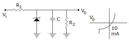
Figure shows a zener circuit and characteristic of the zener used. If R2 is the lowest load resistance, then for proper voltage regulation R1 must be
more than 
more than 
less than
less than
8.
In CC configuration, the output signals has approximately
9.
The PIV of a bridge rectifier is less than that of full wave rectifier with centre tapped transformer.
10.
Zero bias works only with
Quick links
Quantitative Aptitude
Verbal (English)
Reasoning
Programming
Interview
Placement Papers