Electronics and Communication Engineering - Analog Electronics
Exercise : Analog Electronics - Section 6
- Analog Electronics - Section 11
- Analog Electronics - Section 21
- Analog Electronics - Section 20
- Analog Electronics - Section 19
- Analog Electronics - Section 18
- Analog Electronics - Section 17
- Analog Electronics - Section 16
- Analog Electronics - Section 15
- Analog Electronics - Section 14
- Analog Electronics - Section 13
- Analog Electronics - Section 12
- Analog Electronics - Section 1
- Analog Electronics - Section 10
- Analog Electronics - Section 9
- Analog Electronics - Section 8
- Analog Electronics - Section 7
- Analog Electronics - Section 6
- Analog Electronics - Section 5
- Analog Electronics - Section 4
- Analog Electronics - Section 3
- Analog Electronics - Section 2
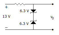
36.
In figure, V0 =
Answer: Option
Explanation:
Output voltage is j 6.3 + 0.7 V.
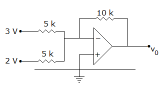
37.
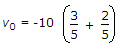
In the op-amp circuit of figure, V0 =
Answer: Option
Explanation:
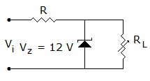
38.
In figure the zener has a resistance of 5 ohms. As the load resistance is varied, the output voltage
Answer: Option
Explanation:
V0 = 12 + Iz x 5, Max Iz = 130 mA, minimum Iz = 10 mA.
39.
Percentage increase in the reverse saturation current of a diode if the temperature is increased from 25°C to 50°C
Answer: Option
Explanation:
 = 2(T2 - T1)/10
 = 2(50-25)/10 x 100% 565.7% .
40.
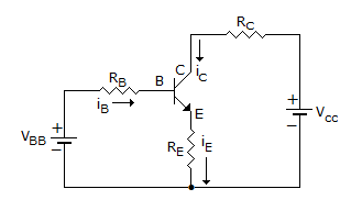
The transistor of following figure in Si diode with a base current of 40 μA and ICBO = 0, if VBB = 6V, RE = 2 kΩ and β = 90, IBQ = 20 μA then IEQ =
Answer: Option
Explanation:
 , ICQ = β IBQ = 90 x 20 μA = 1800 μA.
Quick links
Quantitative Aptitude
Verbal (English)
Reasoning
Programming
Interview
Placement Papers