Electronics and Communication Engineering - Analog Electronics
Exercise : Analog Electronics - Section 6
- Analog Electronics - Section 11
- Analog Electronics - Section 21
- Analog Electronics - Section 20
- Analog Electronics - Section 19
- Analog Electronics - Section 18
- Analog Electronics - Section 17
- Analog Electronics - Section 16
- Analog Electronics - Section 15
- Analog Electronics - Section 14
- Analog Electronics - Section 13
- Analog Electronics - Section 12
- Analog Electronics - Section 1
- Analog Electronics - Section 10
- Analog Electronics - Section 9
- Analog Electronics - Section 8
- Analog Electronics - Section 7
- Analog Electronics - Section 6
- Analog Electronics - Section 5
- Analog Electronics - Section 4
- Analog Electronics - Section 3
- Analog Electronics - Section 2
21.
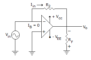
The circuit shown is
Answer: Option
Explanation:
Circuit can be redrawn as.
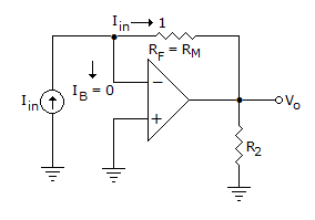
This is an inverting amplifier with inverting terminal virtual ground.
Hence, Vo = - iin RF
This RF is termed as mutual resistance here, Rm.
output voltage with load
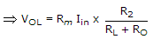
Where R0 is output Resistance of Op-Amp.
if RL >> R0 output terminals become open circuited.
and VoL = Rm.Iin
where Rm work as mutual resistance.
22.
Consider 49 cascaded amplifiers having individual rise time as 2 n sec. 3 n sec. ... 50 n sec. The input waveform rise time is 1 n sec. Then the output signal rise time is given time by (Assume output signal rise time is measured within 10 percent range of the final output signal.)
Answer: Option
Explanation:
Output rise time (tr)  1.1ti02 + t12 + ... + t492,
where t, t2 ... t49 are the individual rise time.
 tr 1.1 (1 ns)2 + (2 ns)2 + (50 ns)2
1.1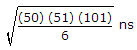 0.228 msec.
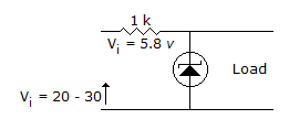
23.
The zener diode in the rectangular circuit shown in the figure has a zener voltage of 5.8 volts and a zener knee current of 0.5 mA. The maximum load current drawn from this circuit ensuring proper functioning over the input voltage range between 20 and 30 volts, is
Answer: Option
Explanation:
It is zener diode, hence 5.8 volt remain constant.
By applying KVL
30 = 1000 Imax + 5.8
Imax = 24.2 mA.
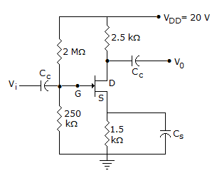
24.
In figure, ID = 4 mA. Then VDS =
Answer: Option
Explanation:
VDS = VD - VS = 10-6 = 4 V.
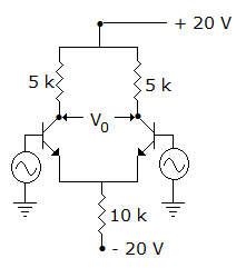
25.
In figure, V0 =
Answer: Option
Explanation:
Both collector terminals are at the same potential.
Quick links
Quantitative Aptitude
Verbal (English)
Reasoning
Programming
Interview
Placement Papers