Electronics and Communication Engineering - Analog Electronics
Exercise : Analog Electronics - Section 4
- Analog Electronics - Section 11
- Analog Electronics - Section 21
- Analog Electronics - Section 20
- Analog Electronics - Section 19
- Analog Electronics - Section 18
- Analog Electronics - Section 17
- Analog Electronics - Section 16
- Analog Electronics - Section 15
- Analog Electronics - Section 14
- Analog Electronics - Section 13
- Analog Electronics - Section 12
- Analog Electronics - Section 1
- Analog Electronics - Section 10
- Analog Electronics - Section 9
- Analog Electronics - Section 8
- Analog Electronics - Section 7
- Analog Electronics - Section 6
- Analog Electronics - Section 5
- Analog Electronics - Section 4
- Analog Electronics - Section 3
- Analog Electronics - Section 2
26.
In figure base current is 10 μA and βdc = 100. Then VE =
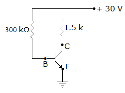
Answer: Option
Explanation:
IC = 1 mA and VCE = 20 - 5 x 103 x 1 x 10-3 = 15 V.
27.
It has been found that in a rectifier circuit with RC filter one RC section reduces ripple by 15%. Two RC sections are used in cascade the reduction in ripple would be
Answer: Option
Explanation:
One filter reduces ripple to 0.15 of initial value. The second filter reduces ripple to 0.15 x 0.15 of initial value.
28.
An op-amp has
Answer: Option
Explanation:
High input impedance ensures minimum loading of source. Low output impedance is required for impedance matching at output.
29.
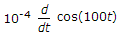
In the figure, assume the op-amp is to be ideal. The output Vo if the circuit is
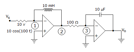
10 cos (100t)
Answer: Option
Explanation:
KCL at mode one.
 ... (1)
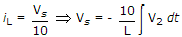
Applying KCL at node (3)
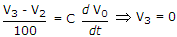
 ... (2)
From (1)

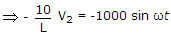
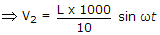
 V2 = 100 L sin ωt
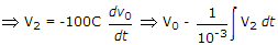
Put value of V2 in equation (2) and solve for V0 .
30.
As the ratio Rf/RL increases the efficiency of a rectifier increases.
Answer: Option
Explanation:
As  increases efficiency decreases.
Quick links
Quantitative Aptitude
Verbal (English)
Reasoning
Programming
Interview
Placement Papers