Electronic Devices - Special-Purpose Op-Amp Circuits - Discussion
Discussion Forum : Special-Purpose Op-Amp Circuits - General Questions (Q.No. 9)
9.
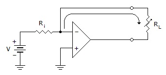
Refer to the given figure. This circuit is a setup for
Discussion:
3 comments Page 1 of 1.
Claude said:
5 years ago
Using KCL in the node : Iin = IL + I.
Iin = input current =(V-0)/ RL,
I = current going to the op-amp,
IL = load current.
Since we know that op-amps have very high input impedance then I would be equal to 0
therefore, Iin=IL + 0 = Vin/Ri, and since both the Vin and Ri are constant, the current in the load will always be constantly creating a constant current source regardless of the value of the load resistance.
Gautham said:
9 years ago
Could someone explain this?
Post your comments here:
Quick links
Quantitative Aptitude
Verbal (English)
Reasoning
Programming
Interview
Placement Papers