Electronic Devices - Oscillator Circuits - Discussion
Discussion Forum : Oscillator Circuits - General Questions (Q.No. 60)
60.
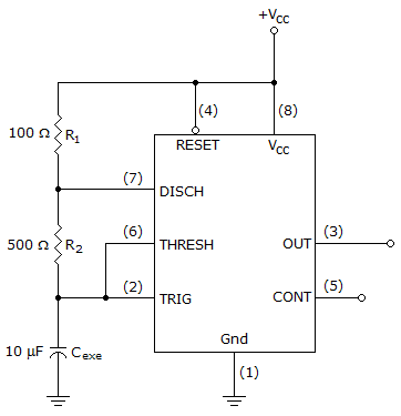
Refer to this figure. Assuming it is configured as an oscillator and if you desired to reduce the duty to less than 50%, the following circuit change would need to be made.
Discussion:
4 comments Page 1 of 1.
Blackfyre said:
3 years ago
Yes, I agree. The diode should be in parallel with R2. Along with the discharge and trigger pin of the IC.
Junjun said:
5 years ago
@Warren.
That is the conventional circuit you are mentioning. But, if you analyze the circuit carefully, the resistors between charging time and discharging time must be equal in value, otherwise, the circuit will have a lower or higher duty cycle. Thus, the best solution is to put a diode across R1.
That is the conventional circuit you are mentioning. But, if you analyze the circuit carefully, the resistors between charging time and discharging time must be equal in value, otherwise, the circuit will have a lower or higher duty cycle. Thus, the best solution is to put a diode across R1.
Warren said:
9 years ago
@Jef.
How that diode should be in parallel with R2?
How that diode should be in parallel with R2?
Jef said:
1 decade ago
The diode should be parallel with R2 not with R1.
(2)
Post your comments here:
Quick links
Quantitative Aptitude
Verbal (English)
Reasoning
Programming
Interview
Placement Papers