Digital Electronics - Signals and Switches - Discussion
Discussion Forum : Signals and Switches - General Questions (Q.No. 12)
12.
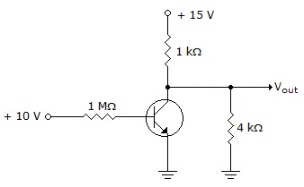
What is the output voltage from the circuit in the given figure?
Discussion:
9 comments Page 1 of 1.
Ashish said:
1 decade ago
Please explain me the ans.
Meakdjani said:
1 decade ago
Whenever a neg(-) sign apply at base and Vcc at collector then transistor is switched on and voltage appear at output.
E.g. (Vce=Vcc-IR)
E.g. (Vce=Vcc-IR)
Lal said:
1 decade ago
One logic is there here basically at high resistance tr does not conduct. I/p resistance is in mega-ohm.
Venu said:
1 decade ago
Here transistor is forward bias so total voltage is going to the ground so output voltage will be zero.
Shreyas said:
1 decade ago
In this figure the voltage at base terminal is enough to switch on transistor, and if its on the voltage across Vce=0v and Vce=Vout=0v.
Mahabub said:
1 decade ago
Vce=Vcc-Ic*Rc.
When the tr. conduct(due to positive I/P or base-emitter voltage here CE config. ) the collector current increases and voltage drop across Rc increases which in turns decreases Vce bcz Vcc is fixed. That's why when input voltage is high then output voltage Vce is 0 i.e 0v.
When the tr. conduct(due to positive I/P or base-emitter voltage here CE config. ) the collector current increases and voltage drop across Rc increases which in turns decreases Vce bcz Vcc is fixed. That's why when input voltage is high then output voltage Vce is 0 i.e 0v.
Vishnu said:
9 years ago
I think this transistor is used here as switching. So the current goes towards ground. So op is 0.
Pogi said:
6 years ago
It is because Rb is 1 megaohms, no current will pass through.
Jerick said:
4 years ago
That circuit is an inverter circuit. So, when the input voltage is HIGH, the output voltage will be LOW. That's why the answer is 0V.
Post your comments here:
Quick links
Quantitative Aptitude
Verbal (English)
Reasoning
Programming
Interview
Placement Papers