Digital Electronics - Combinational Logic Analysis - Discussion
Discussion Forum : Combinational Logic Analysis - General Questions (Q.No. 7)
7.
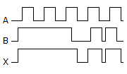
The following waveform pattern is for a(n) ________.
Discussion:
4 comments Page 1 of 1.
Patricia said:
9 years ago
Since it is pulses it corresponds to 0's and 1's.
Input A= 101010101
Input B= 111110111
Ouput x shows= 111110111, which corresponds to a characteristic of an OR Gate.
Input A= 101010101
Input B= 111110111
Ouput x shows= 111110111, which corresponds to a characteristic of an OR Gate.
Deepanjali said:
10 years ago
Please explain it.
Sushmitha said:
1 decade ago
Please someone explain it. I can't understand.
Garima said:
1 decade ago
Because in the timing diagram,
Whenever a=0 & b=0 then only x=0 else output is 1.
Thus it follows the truth table of OR gate.
Whenever a=0 & b=0 then only x=0 else output is 1.
Thus it follows the truth table of OR gate.
(1)
Post your comments here:
Quick links
Quantitative Aptitude
Verbal (English)
Reasoning
Programming
Interview
Placement Papers