Civil Engineering - Strength of Materials - Discussion
Discussion Forum : Strength of Materials - Section 5 (Q.No. 6)
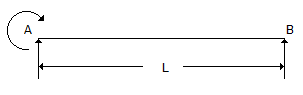
6.
The B.M. diagram of the beam shown in below figure, is
Discussion:
21 comments Page 1 of 3.
Joseph Aspidin said:
5 years ago
Anyone who says BM at A is equal to M is out of their Mind.
At SS, BM =0 always because it just can't resist the applied moment. BM will be zero at both A and B.
However, BMD will be triangular. Consider it as a case of SS beam with the applied moment at the middle. This is one and the same thing.
At SS, BM =0 always because it just can't resist the applied moment. BM will be zero at both A and B.
However, BMD will be triangular. Consider it as a case of SS beam with the applied moment at the middle. This is one and the same thing.
KSHITIJ said:
1 decade ago
Wrong answer, it should be triangular.
Proof:
Moment at a section x from left end is given by:
M = m-m*(x/l).
m = moment applied at left end.
So at x = 0; M = m.
At x = L; M = 0.
Proof:
Moment at a section x from left end is given by:
M = m-m*(x/l).
m = moment applied at left end.
So at x = 0; M = m.
At x = L; M = 0.
Reshu agrawal said:
1 decade ago
Yes, the correct answer is a triangle.
Ra + Rb = 0 (because there is no any load).
Bending moment on support b =0.
BM on support A = M (moment).
So, the diagram will be a triangle.
Ra + Rb = 0 (because there is no any load).
Bending moment on support b =0.
BM on support A = M (moment).
So, the diagram will be a triangle.
Sandeep Polaki said:
10 years ago
The answer can be rectangular only if the question would be, what is the shape of the shear force diagram rather than a bending moment diagram?
Nepali said:
8 years ago
For the moment at A: BMD is a rectangle.
For the reaction at A: BMD is a triangle.
Hence net BMD is trapezium, so the option C is correct.
For the reaction at A: BMD is a triangle.
Hence net BMD is trapezium, so the option C is correct.
Bahaa said:
10 years ago
Having the shear is constant and we have an applied moment of one end, the B.M needs to be of a triangular shape.
Joydeep said:
8 years ago
@All.
SF diagram will be a straight line, here no load is applied & BM diagram will be a triangle.
SF diagram will be a straight line, here no load is applied & BM diagram will be a triangle.
Sanat kumar said:
5 years ago
At A, moment is M.
At B, moment is 0.
It should be drawn to a Triangle.
At B, moment is 0.
It should be drawn to a Triangle.
Arun chauhan said:
10 years ago
Shear diagram will be rectangular but b, m will be in triangular shape.
Akash.choudhary said:
1 decade ago
Yes it should be triangular because the moment acting on the support.
Post your comments here:
Quick links
Quantitative Aptitude
Verbal (English)
Reasoning
Programming
Interview
Placement Papers