Online Electronic Devices Test - Electronic Devices Test - Random
Instruction:
- This is a FREE online test. Beware of scammers who ask for money to attend this test.
- Total number of questions: 20.
- Time allotted: 30 minutes.
- Each question carries 1 mark; there are no negative marks.
- DO NOT refresh the page.
- All the best!
Marks : 2/20
Total number of questions
20
Number of answered questions
0
Number of unanswered questions
20
Test Review : View answers and explanation for this test.
1.
A silicon diode in a half-wave rectifier has a barrier potential of 0.7 V. This has the effect of
Your Answer: Option
(Not Answered)
Correct Answer: Option
Discuss about this problem : Discuss in Forum
Learn more problems on : Diode Applications
2.
The intersection of the load line with the characteristic curve determines the ________ of the system.
Your Answer: Option
(Not Answered)
Correct Answer: Option
Discuss about this problem : Discuss in Forum
Learn more problems on : Diode Applications
3.
In what decade was the first transistor created?
Your Answer: Option
(Not Answered)
Correct Answer: Option
Discuss about this problem : Discuss in Forum
Learn more problems on : BJT Devices
4.
In a transistor-switching network, the level of the resistance between the collector and emitter is ________ at the saturation and is ________at the cutoff.
Your Answer: Option
(Not Answered)
Correct Answer: Option
Discuss about this problem : Discuss in Forum
Learn more problems on : DC Biasing-BJTs
5.
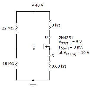
Calculate VD.
Your Answer: Option
(Not Answered)
Correct Answer: Option
Discuss about this problem : Discuss in Forum
Learn more problems on : DC Biasing-FETs
6.
In a feedback-bias configuration, the slope of the dc load line is controlled by ________.
Your Answer: Option
(Not Answered)
Correct Answer: Option
Discuss about this problem : Discuss in Forum
Learn more problems on : DC Biasing-FETs
7.
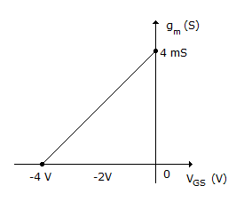
Referring to the following figure, calculate gm for VGSQ = –1.25 V.
Your Answer: Option
(Not Answered)
Correct Answer: Option
Discuss about this problem : Discuss in Forum
Learn more problems on : FET Amplifiers
8.
Which of the following is a required condition to simplify the equations for Zo and Av for the self-bias configuration?
rd  10RD
10RD
10RDrd = RD
rd  10RD
10RD
10RDNone of the above
Your Answer: Option
(Not Answered)
Correct Answer: Option
Discuss about this problem : Discuss in Forum
Learn more problems on : FET Amplifiers
9.
The ________ controls the ________ of an FET.
Your Answer: Option
(Not Answered)
Correct Answer: Option
Discuss about this problem : Discuss in Forum
Learn more problems on : FET Amplifiers
10.
What is the range of the capacitor Cds?
Your Answer: Option
(Not Answered)
Correct Answer: Option
Discuss about this problem : Discuss in Forum
Learn more problems on : BJT and FET Frequency Response
11.
The output voltage of a voltage buffer is ________ with the input voltage.
Your Answer: Option
(Not Answered)
Correct Answer: Option
Discuss about this problem : Discuss in Forum
Learn more problems on : Op-Amp Applications
12.
What is (are) the level(s) of the input voltage to a ladder-network conversion?
Your Answer: Option
(Not Answered)
Correct Answer: Option
Discuss about this problem : Discuss in Forum
Learn more problems on : Linear-Digital ICs
13.
The ________ the ac variation with respect to the dc level, the ________ the filter circuit's operation.
Your Answer: Option
(Not Answered)
Correct Answer: Option
Discuss about this problem : Discuss in Forum
Learn more problems on : Voltage Regulators
14.
The ________ the diode conduction time, the ________ the amount of the charging current through the capacitor filter.
Your Answer: Option
(Not Answered)
Correct Answer: Option
Discuss about this problem : Discuss in Forum
Learn more problems on : Voltage Regulators
15.
Refer to this figure. Which symbol is correct for a zener diode?

Your Answer: Option
(Not Answered)
Correct Answer: Option
Discuss about this problem : Discuss in Forum
Learn more problems on : Special-Purpose Diodes
16.
Refer to the given figure. The most probable cause of trouble, if any, from these voltage measurements is

Your Answer: Option
(Not Answered)
Correct Answer: Option
Discuss about this problem : Discuss in Forum
Learn more problems on : Transistor Bias Circuits
17.
The Q-point in a JFET with voltage-divider bias is more stable than in a self-biased JFET.
Your Answer: Option
(Not Answered)
Correct Answer: Option
Discuss about this problem : Discuss in Forum
Learn more problems on : Field-Effect Transistors
18.
An RC network has a roll-off of 20 dB per decade. What is the total attenuation between the output voltage in the midrange of the passband as compared to the output voltage at a frequency of 10 times fc?
Your Answer: Option
(Not Answered)
Correct Answer: Option
Discuss about this problem : Discuss in Forum
Learn more problems on : Amplifier Frequency Response
19.
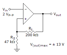
Refer to the given figure. Determine the lower trigger point.
Your Answer: Option
(Not Answered)
Correct Answer: Option
Discuss about this problem : Discuss in Forum
Learn more problems on : Basic Op-Amp Circuits
20.
Identify the frequency response curve for a band-pass filter.

Your Answer: Option
(Not Answered)
Correct Answer: Option
Discuss about this problem : Discuss in Forum
Learn more problems on : Active Filters
*** END OF THE TEST ***
Time Left: 00:29:56
Post your test result / feedback here:
Quick links
Quantitative Aptitude
Verbal (English)
Reasoning
Programming
Interview
Placement Papers