Circuit Simulator - Summing Amplifier
Why should I learn to use the circuit simulator to design Summing Amplifier circuits?
Learn how to use circuit simulator software to design your own Summing Amplifier circuits.
Where can I get a Summing Amplifier circuit diagram with an explanation?
IndiaBIX provides numerous Summing Amplifier circuit diagrams with detailed explanations and working principles.
How do I design a Summing Amplifier circuit with this circuit simulator?
You can easily design Summing Amplifier circuit diagrams by practising with the given circuit simulator. With this online circuit simulator, you can design and simulate your own electronic circuits.
Summing Amplifier
Circuit Description:
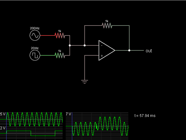
This circuit outputs the (inverted) sum of the voltages of two input signals. In this case, the first input is a 200 Hz sine wave, and the second input is a 20 Hz square wave.
The op-amp attempts to keep its – input at the same voltage as the + input (which is at ground). So, both input signals are driving 1k resistors whose other end is at ground. The current across the third resistor is the sum of the two currents, so the voltage drop must be equal to the sum of the two voltage drops, which is the (negative) sum of the input voltages.
The op-amp attempts to keep its – input at the same voltage as the + input (which is at ground). So, both input signals are driving 1k resistors whose other end is at ground. The current across the third resistor is the sum of the two currents, so the voltage drop must be equal to the sum of the two voltage drops, which is the (negative) sum of the input voltages.
Discussion:
Be the first person to comment on this question !
Post your comments here:
Quick links
Quantitative Aptitude
Verbal (English)
Reasoning
Programming
Interview
Placement Papers