Circuit Simulator - Resistors
Resistors

Circuit Description:
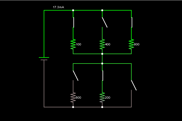
This is a simple resistive circuit. The green color indicates positive voltage, and the gray color indicates ground (or earth). The movement of yellow dots indicates current (in the conventional direction). The left side of the circuit shows a voltage source providing 5 volts, and the current flows through a number of switches and resistors to the right. The amount of resistance in ohms is shown to the right of each resistor.
To turn a switch on or off, just click on it. If you move the mouse over any component of the circuit, you will see a short description of that component and its current state in the lower right corner of the window.
If there is only one switch closed on top and one closed on the bottom, then there is a single path through the circuit, and by Ohm's Law, the current will be equal to 5V divided by the total resistance through the current path.
If there are multiple current paths, you may have you may have resistors in parallel.
Discussion:
13 comments Page 2 of 2.
Avinash aachari said:
1 decade ago
Very nice guidance for learners.
(7)
Satvinder singh said:
1 decade ago
Superb interview guideline.
(2)
Vidya said:
2 decades ago
Very nice.
(2)
Post your comments here:
Quick links
Quantitative Aptitude
Verbal (English)
Reasoning
Programming
Interview
Placement Papers