Electronics and Communication Engineering - Digital Electronics - Discussion
Discussion Forum : Digital Electronics - Section 24 (Q.No. 2)
2.
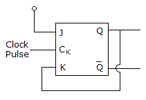
In the given figure assume that initially Q = 1 with Clock Pulses being given, the subsequent states of Q will be
Discussion:
12 comments Page 2 of 2.
Vishnu said:
1 year ago
Final Result:
The output Q toggles between 1 and 0 on every clock pulse.
Hence, the subsequent states of Q will be:
1 → 0 → 1 → 0 → 1 → 0 → ...
This forms a T-flip flop (toggle behaviour) using a JK flip-flop where:
J = Q̅
K = Q.
The output Q toggles between 1 and 0 on every clock pulse.
Hence, the subsequent states of Q will be:
1 → 0 → 1 → 0 → 1 → 0 → ...
This forms a T-flip flop (toggle behaviour) using a JK flip-flop where:
J = Q̅
K = Q.
Srishti said:
10 months ago
The figure shows a JK flip-flop where the K input is directly connected to Q (the current output), and the J input is connected to a constant logic high (1).
Initially, Q = 1.
On each clock pulse, the state transitions depend on the values of J and K.
State Analysis:
J = 1 at all times.
K = Q (feedback connection).
For Q = 1:
J = 1, K = 1 (since Q = 1)
A JK flip-flop with J = 1, K = 1 will toggle its output.
So, after the first clock pulse, Q becomes 0.
For Q = 0:
J = 1, K = 0 (since K = Q = 0)
JK flip-flop with J = 1, K = 0 sets Q to 1 on the clock edge.
Q goes to 1 again.
This pattern repeats with each clock pulse.
Sequence of Q:
The output Q will alternate between 1 and 0 on every clock pulse:
1, 0, 1, 0, 1, 0, ...
Post your comments here:
Quick links
Quantitative Aptitude
Verbal (English)
Reasoning
Programming
Interview
Placement Papers