Circuit Simulator - Voltage-Controlled Oscillator
Why should I learn to use the circuit simulator to design Voltage-Controlled Oscillator circuits?
Learn how to use circuit simulator software to design your own Voltage-Controlled Oscillator circuits.
Where can I get a Voltage-Controlled Oscillator circuit diagram with an explanation?
IndiaBIX provides numerous Voltage-Controlled Oscillator circuit diagrams with detailed explanations and working principles.
How do I design a Voltage-Controlled Oscillator circuit with this circuit simulator?
You can easily design Voltage-Controlled Oscillator circuit diagrams by practising with the given circuit simulator. With this online circuit simulator, you can design and simulate your own electronic circuits.
Voltage-Controlled Oscillator
Circuit Description:
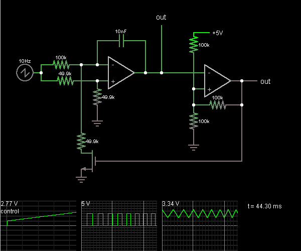
This circuit is a voltage-controlled oscillator, which is an oscillator whose frequency is determined by a control voltage. A 10 Hz sawtooth oscillator provides the control voltage in this case; this causes the frequency to rise slowly until it hits a maximum and then falls back to the starting frequency.
The first op-amp is an integrator. A voltage divider puts the + input at half the control voltage. The op-amp attempts to keep its – input at the same voltage, which requires a current flow across the 100k to ensure that its voltage drop is half the control voltage.
When the MOSFET at the bottom is on, the current from the 100k goes through the MOSFET. Since the 49.9k resistor has the same voltage drop as the 100k but half the resistance, it must have twice as much current flowing through it. The additional current comes from the capacitor, charging it, so the first op-amp must provide a steadily rising output voltage to source this current.
When the MOSFET at the bottom is off, the current from the 100k goes through the capacitor, discharging it, so a steadily falling output voltage is needed from the first op-amp. The third scope shows the output voltage; it looks like a triangle wave.
The second op-amp is a Schmitt trigger. It takes the triangle wave as input. When the input voltage rises above the threshold of 3.33 V, it outputs 5 V and the threshold voltage falls to 1.67 V. When the input voltage falls below that, the output goes to 0 V and the threshold moves back up. The output is a square wave. It's connected to the MOSFET, causing the integrator to raise or lower its output voltage as needed.
Discussion:
1 comments Page 1 of 1.
Esben said:
1 decade ago
If using this with a variable DC-source, is there any way to calculate, how much the frequency will increase pr.volt?
(6)
Post your comments here:
Quick links
Quantitative Aptitude
Verbal (English)
Reasoning
Programming
Interview
Placement Papers