Circuit Simulator - Howland Current Source
Why should I learn to use the circuit simulator to design Howland Current Source circuits?
Learn how to use circuit simulator software to design your own Howland Current Source circuits.
Where can I get a Howland Current Source circuit diagram with an explanation?
IndiaBIX provides numerous Howland Current Source circuit diagrams with detailed explanations and working principles.
How do I design a Howland Current Source circuit with this circuit simulator?
You can easily design Howland Current Source circuit diagrams by practising with the given circuit simulator. With this online circuit simulator, you can design and simulate your own electronic circuits.
Howland Current Source
Circuit Description:
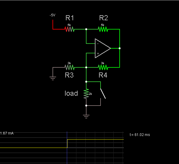
This circuit shows a current source. The current through the load is the same regardless of the position of the switch.
The op-amp attempts to keep the voltages at both terminals the same, so V– = V+. Call V1 the voltage across R1, and I1 the current across R1. Then V2 = V4. Since I1 = I2 and R1 = R2, V1 = V2 = V4.
V– = V+ = V1 - 5V
I3 = V+/R3 = (V1 - 5V)/R3.
I4 = I3 + Iload.
I4 = V4/R4 = V1/R3.
V1/R3 = (V1 - 5V)/R3 + Iload
Iload = 5V / R3 = 1.67 mA
Discussion:
5 comments Page 1 of 1.
SPF said:
1 decade ago
Sorry, doesn't work. Did you actually try it on SPICE?
(7)
S_eng said:
1 decade ago
The demonstration circuit is flawed, and contrary to the text statement, and as drawn, the current in the load WILL vary. It would be better to show an additional load switched in, in series with the first load, thus showing that the circuit delivers a constant value current despite the changing load.
(3)
Someone said:
1 decade ago
It stops because when you flip the switch, you created a path where resistance equals 0.
(7)
Tom said:
1 decade ago
Why does the current stop in resistor R3 when the switch is closed? Is it just so small that it does not show? There should be some current unless these are theoretical Zero resistance switch and conductors ("wires").
(4)
Nick said:
1 decade ago
That's Widlar's current source. Still nicely done.
(5)
Post your comments here:
Quick links
Quantitative Aptitude
Verbal (English)
Reasoning
Programming
Interview
Placement Papers