Circuit Simulator - 555 Pulse Width Modulator
Why should I learn to use the circuit simulator to design 555 Pulse Width Modulator circuits?
Learn how to use circuit simulator software to design your own 555 Pulse Width Modulator circuits.
Where can I get a 555 Pulse Width Modulator circuit diagram with an explanation?
IndiaBIX provides numerous 555 Pulse Width Modulator circuit diagrams with detailed explanations and working principles.
How do I design a 555 Pulse Width Modulator circuit with this circuit simulator?
You can easily design 555 Pulse Width Modulator circuit diagrams by practising with the given circuit simulator. With this online circuit simulator, you can design and simulate your own electronic circuits.
555 Pulse Width Modulator
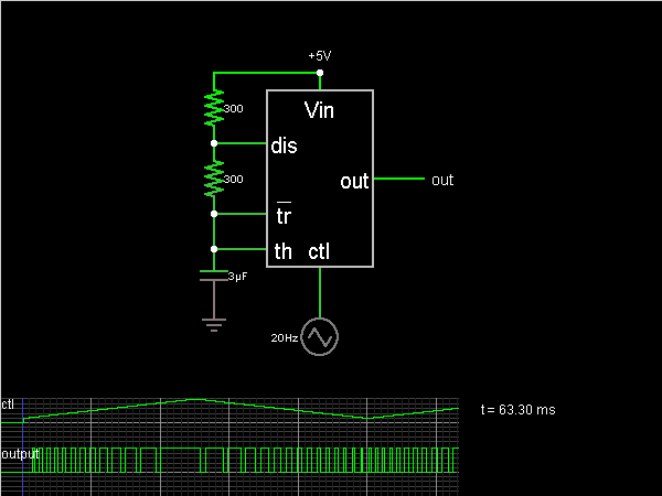
Circuit Description:
This circuit encodes a voltage with pulse-width modulation using a 555 timer chip. The width of the output pulses varies depending on a control voltage.
The width of the pulses is set by a triangle wave oscillator connected to the "ctl" input of the 555. The rest of the circuit is just like the square wave oscillator. By applying a voltage to the "ctl" input (normally 2/3 Vin), we can control the voltage which ends a timing interval. When the "th" input reaches this value, the output goes low. So the 555 will oscillate faster when the ctl input is lower.
The width of the pulses is set by a triangle wave oscillator connected to the "ctl" input of the 555. The rest of the circuit is just like the square wave oscillator. By applying a voltage to the "ctl" input (normally 2/3 Vin), we can control the voltage which ends a timing interval. When the "th" input reaches this value, the output goes low. So the 555 will oscillate faster when the ctl input is lower.
Discussion:
Be the first person to comment on this question !
Post your comments here:
Quick links
Quantitative Aptitude
Verbal (English)
Reasoning
Programming
Interview
Placement Papers